In the previous part of this post, we looked at synchronizing the camera settings between Blender and Unity so that they render objects in the same perspective. In this post, we build upon this to result to render the Unity objects into the pre-rendered background.
Exporting depth values

Upper part: The rendered image, lower part: the depth image
In a first step, we have to export the depth of our image along with the rendered image. Blender makes the depth-value of the image available to you when you use the nodes editor for setting up the rendering.
In the image, you see the node network that in the end proved to be what I wanted.
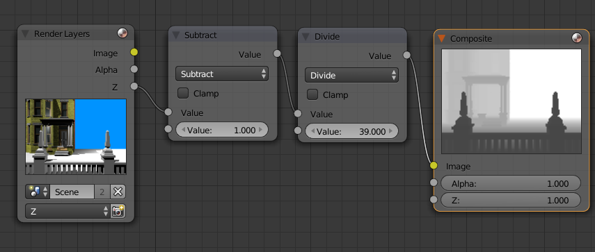
The node settings to render the depth image. Don’t forget to set the render settings to RAW in the scene settings.
Here’s a short explanation:Â The camera is set to a far clip distance of 40 and a near clip distance of 1. What I want is a linear distribution of z-value in the range between the near and far clipping planes. The z-Buffer in Blender is a floating point number that is linear between the camera position at z=0 and into the screen. So, to map the incoming z values to the interval 0-1, we have to first subtract 1 (the distance of the near clipping plane) and divide by 39 (far – near). This way, we get a correct grayscale image.
There are several sources on the net that either propose to use a Map Values or a Normalize node. Both will create an image that might seem correct and that might work for some applications, however, they both have their disadvantages. The normalize node will take the lowest and highest value and map them to the interval [0,1]. However, this is only correct if you have objects at the complete ends of the clipping region. You want an object at the far clipping plane to be almost white in the depth image. Instead, if you have objects in a very narrow range, it won’t cover the actual clipping area. The Map values node will actually do the right operation, but especially the division is harder to get correct as you have to enter 1/39 as a decimal number.
There have been some forum discussions that have been priceless in finding out relevant information. For example, it is imperative that you have the “RAW” render setting in the scene settings set. I found the most useful information in these two forum posts on Elysiun and Unity3D.com.
During debugging I found out some other funny things about Blender. You can view the depth buffer in the image viewer, but taking this image will actually not gain you that much. For whatever reason, it does the correct operation, but then squares the depth value, making everything darker that it should be.
Rendering depth in Unity
Once you have exported the image, the next part is getting it into Unity. This is achieved by importing it as an Advanced texture, ideally with no compression. After importing, there are two major techniques that could be used to composit the image:
- We could adjust all shaders in our scene, to sample the depth image before writing something in the depth shader. If we find that we are hidden by the image, we can discard the pixel.
- We first write the depth buffer from the image and then render our realtime geometry into the image. This way, when we try to write to a pixel that is infront of the realtime rendered geometry, it is discarded.
Number 2 has by far the advantage. First, we don’t have to adapt any shaders to work with this system. Second, the graphics card will already discard the pixel if it fails the z-test and our fragment shader will never be run on occluded pixels. Third, we don’t have to send the depth image to the graphics card for each object that we want to render. Therefore, number 2 is implemented. For the realization, we first render a screen-sized quad with the image and the depth image, filling the depth buffer. Then, we have a second camera that renders the geometry. This camera has its clearing flags set to “None”, since we don’t want to reset either the color or the depth buffer that is set to the pre-rendered depth and image.
To compute the depth, we have to put a little bit of work into figuring out where in the graphics pipeline we are. What we get from the image is a linearized z-value between the near and far clipping plane. Normally, we have z in screen space, which results from a perspective projection and division from eye space. This perspective division makes the z-buffer values be distributed non-linearly. And we want this normal non-linear z-Buffer value as the output of our shaders which initializes the depth buffer.
The way to make this work is by projecting the depth back into the eye space and then carrying out the perspective transform and division in our fragment shader. This way, we get the same z-value as we would have gotten had the object been rendered in Unity itself.
Collision

The collision geometry for the demo scene in Unity
Even though we do not render any geometry from Blender, it is useful to create some collision geometry to use in Unity. For example, I have re-created the outlines of the structures in the demo with boxes and exported these boxes. For easier navigation in the Blender scene, the collision geometry is on a separate layer than the rendered geometry.
In Unity we can either disable the mesh renderers for the collision geometry or have them be masked out from both cameras by placing them in a “Colliders” layer and not rendering this layer in the two cameras.
Result
As you can try out for yourself, the system works, the character will walk correctly behind the fence in the foreground. There are some potential improvements, though:
- Depth values are very coarse. Since we are working with grayscale textures, we can only encode 256 levels of depth. This can already help us since we will make sure with colliders that characters will not pass through objects, but we always have to watch out for rounding errors. Note that we can choose different clip values in Unity that we did in Blender – we only have to supply the correct input values to our Shader.
This problem could be improved if we used 32 bit textures which encode a single 32 bit float per pixel. This could for example be exported using the OpenEXR format in Blender. In Unity, we could encode and decode the values in a similar way as positions were encoded in the Self-Building Structures Demo. - Light and Shadows. So far, I have not looked into synchronizing the light sources between Blender and Unity. Furthermore, I have not looked into shadows. We have two shadow sources to consider: First, we have the shadows that are in the pre-rendered image and that should also fall onto the character. Second, we have the shaders the character casts on the pre-rendered geometry. A simple way for the second one would be something as Broken Age does it, drawing a round shadow on the floor.
A solution for both types of shadows might be to do shadow mapping. In shadow mapping, we use a depth buffer rendered from the light source to determine shadow. We could use a depth buffer exported from Blender with the static geometry’s depth as seen from the light source to compute shadows that have been cast by the character and also to compute if the character is in shadow.
The source code for this project is available on my github page.
Used assets and further links:
The following assets have been used for the demo scene:
- “Simple fence” by evilvisitor on BlendSwap
- “Brick Wall” by Andrew Kator & Jennifer Legaz
- “Queen Anne Style House”  by Andrew Kator & Jennifer Legaz
- Grass Texture by Simon Murray
- The demo guy that comes with the Unity3D third-person controller
Some more links if you want to go further into the topic: