This post is part three of three in the post series on my re-implementation of the GDC talk “The Inner Workings of Fortnite’s Shader Based Procedural Animationsâ€. For the other parts, click here.
This shader one is definitely the most involved of the three in the presentation. It is used to visualize the effect of walls which seem to build themselves, with pieces flying from the ground to attach themselves to the wall under construction.
The basis for this shader is a 3DS MAX script by Epic called Pivot Painter. It is used to encode the pivot positions of objects in a hierarchy after the hierarchy has been joined as a single mesh. In the demos by Epic, it is used to create leaves in trees which are modelled as single objects and then joined together. The following diagram shows this: To the game engine, the whole of the object (e.g. a wall) is one mesh. However, by encoding the necessary information (the pivot and the local x-Axis of each sub-object) and referencing this information at each vertex, we can animate the sub-objects in the shader as if they were individual meshes.
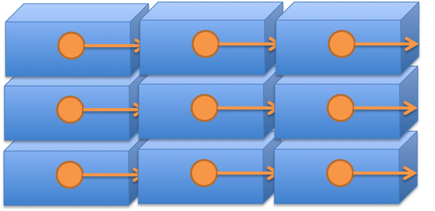
The structure of the object. Each sub-object saves its local origin and the local x-axis. Unity receives it as one mesh.
Let’s assume for the first part of this article that we have such a system. Then we can compose our animation from the same elements as Lindquist explains. These are the following:
- A downward translation. This is pretty much the easiest, as it is not concerned with the local pivot position of the vertices.
- An outward translation. A bit more involved, as it includes a flight path which determines if the object should approach the wall from the front or the back.
- An outward translation away from the center: For this one, we take the vector from the pivot to the center of the target object and use it to push elements outward, resulting in the look of an explosion away from the center of the object.
- A rotation: For this one, we need the Pivot Painter, as we need to figure out around which point and which axis the object should turn. Then it’s a matter of rotating the vertices of the object around the pivot.
These are the basic animation elements. In the system by Epic, they are combined to animate over a value that goes from 0 to 1. To create different speeds, you can add parameters that control how much horizontal/vertical offset is applied etc.
There are two more components to the effect:
- The warp: The result of this effect is to have the parts of the object to appear to be “ripped away” from the overall shape, as if their center was moving faster than their rest. The implementation has some nice thinking to it. Similar to the bounce effect, we do a distance calculation from the pivot to the input vertex. Then, this distance is used to send the animation values “forward” in time, resulting in some parts of the object being further along in the animation than the rest. Nice thinking there, and it works like a charm. One aspect that you have to respect is that objects have to have enough vertices for this effect to be visible. E.g. if you have just a box with no subdivisions, you will not see any effect.
- Culling: Objects that are below the ground or are flying and are close to the ground are masked out, by using a grayscale noise animation to result in a look of disintegration. The way the calculations work will ensure that objects that are simply close to the ground in their normal position on the wall are not faded out, by taking into consideration the animation data.

The animation components of the effect
That was a lot of operations! The result looks pretty nice, though!
The second part of getting this to work was re-build the Pivot Painter tool. I decided to use Blender, since this is the tool I used most often. The first step on this road was to encode the relevant information in Blender. Pivot painter uses several UV-channels to encode the necessary information.
However, this will not work in Unity, as so far, we only get two UV channels, and they would normally be used for the diffuse texture and the normal map/lightmap. To boot, the system will encode the sub-object’s x-axis in the vertex color, taking the possibility to color our objects simply. In the beginning, I used the UV channels nevertheless and simply colored the objects in the shaders. Still I was up for the challenge and decided to encode the necessary information in a texture. I don’t think this is very performant, but as this was an exercise in writing shaders, it was still a very interesting challenge.
I decided to give the first UV channel to Unity to do normal texture mapping and use the second UV channel for mapping into a texture that encoded the rest of the information. I step through the vertices of the models and keep track of the number. The number is saved into the second UV channel. Then, the values of the pivot (XYZ), the local X-axis (XYZ) and the animation order and flight path (1 float) are encoded into the colors of the texture. This is done in a way that is compatible to Unity’s built-in function DecodeFloatRGBA. Therefore, each sub-object takes up 7 pixels in the texture.

The architecture of the Blender export and the data transferred to Unity
Then, in the shader, the values are loaded from the texture using the CG function tex2Dlod, which will not sample a texture at continuous points using interpolation, but instead at a discrete integer/pixel location. This way, I was able to find the correct values again. This opens up the system for much more information beyond the one provided by Pivot Painter, which might lead to other interesting ideas. Animation order is handled by displacing each animated component so that each sub-object is animated between 0 and 1 at different points in the animation.
Some lessons I learned in writing the shaders are the following:
- Unless you need the full implementation, use Unity’s surface shaders, since they will work nicely together e.g. with the shadow system of Unity and save you some work on writing parts of the shader you might not need.
- Think of shader-driving values both as functions between 0 and 1 and of black and white. Both ways of seeing them can have advantages. For debugging purposes, it’s quite easy to visualize values as black and white, and you can easily see what value they have.
- Think about how the input values are modulated and how the functions you are working with are shaped. For example, the warp effect is a nice example: Based on the distance to the pivot, we sample our animation function at different points “ahead of time” to result in the look of the center moving faster than the rest.
- Unreal’s node-based shader composing makes this case a lot easier to understand. The way the shader is written down, it handles a lot of things sequentially, feeding on the output of the last step. In a node-based system, you can see this chain of effects easier.
You can find the source of the demo on github, like the other two shaders. There’s also a blender project including the exporter, which includes a short readme text file to get you started. This part includes a wood texture by shadowh3.